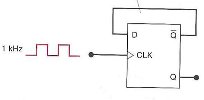

As you can observe from the timing diagram, the counter counts from o0 to 11. The problem of race around condition can solved by edge triggering flip flop. The change of state of flip-flops for each occurrence of the clock pulse is shown in the below timing diagram. Flip flops SR, JK, T, D, Master/Slave FF operation and excitation. This output again toggles, when the output of JK FF1 goes high HIGH. When the JK FF2 gets triggered, it produces a toggled output.Īs we have assumed the initial state of JK FF2 as Q B = 0, the output will get toggled to Q B = 1. Whenever the Q A output goes high, at the falling edge of its output, the JK FF2 will get triggered. The output of the first flip-flop(JK FF1) is given as a clock pulse input for the second flip-flop(JK FF2). The toggling of JK FF1 continues for each clock pulse. For the next clock pulse, again JK FF1 will toggle its output to logic 0. During the first clock pulse, that is at the falling edge of the clock pulse, JK FF1 will toggle its output state to logic 1. Let us assume the initial state of flip-flop as Q BQ A = 00. These parameters are also valid for other configurations of. Develop a timing diagram showing the Q output of each flip-flop, and determine the total propagation delay time from the triggering edge of a clock pulse until a corresponding change can occur in the state of Q3, Also determine the maximum clock frequency at which the counter can be operated. In this section we describe the key parameters of a positive edge triggered D flip-flop circuit. The clock pulse is digitally counted at the output Q A and Q B, where Q A is the Least significant bit(LSB) and Q B is the most significant bit(MSB). Each flip-flop is negative edge-triggered and has a propagation delay for 10 ns.

The HIGH or logic 1 is maintained at the T-input of both flip-flops. The output(Q A) of the first flip-flop is fed as the clock input for the second flip-flop. SPI is a good example of a communication protocol that operates this way.The clock pulse input is given to the first flip-flop only. It means that the latch's output change with a change in input levels and the flip-flop's output only change when there is an edge of controlling signal.

Flip 3D connector and drill the 2 holes Different cases have different tolerances, the 3d block can be a loose or tight. It is also possible to use a negative edge triggered D Type flip-flop to make a negative edge triggered JK flip-flop by this method. That way, there is an entire half clock cycle for the signal to stabilize before it will be read, and slowing down the clock gives more time for outputs to stabilize. This circuit is a edge-triggered D flip-flop. This circuit also makes use of the asynchronous SET and RESET inputs of the D Type flip-flop, and because the D Type is edge triggered, this version of a JK flip flop is truly edge (not level) triggered.

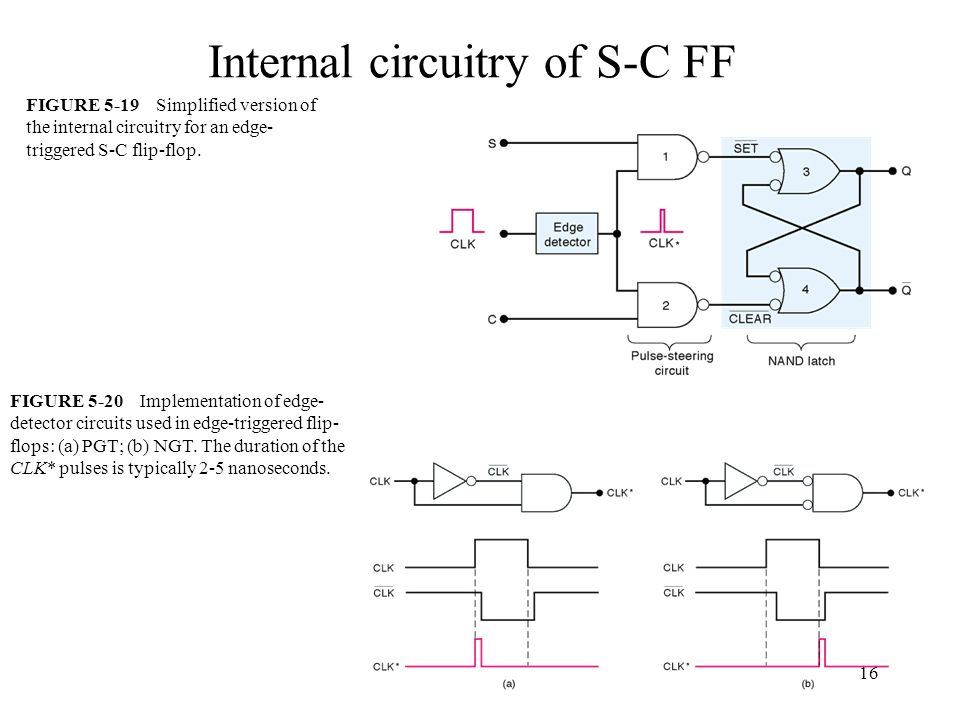
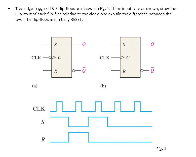
#IN PROBLEM 5 16 WE SAW HOW AN EDGE TRIGGERED FLIP FLOP UPDATE#
However, for low speed buses routed on PCBs, there is another solution: update outputs on the negative clock edge, and latch inputs on the positive edge. On integrated circuits, FPGAs, and high speed interconnects, this is handled by careful clock routing and detailed knowledge of the setup and hold times of the flip flops, as well as their propagation delay. Note that this problem is independent of the clock frequency, slowing down the clock doesn't fix it, only fixing the relative delays will help. If the clock has more delay (due to trace length or capacitive loading) than the signal, then the second flip-flop can miss the value. If both flip-flops update on a rising edge, then the second one will be sampling its input at the same time the first is updating the output. This is an issue when you have one flip-flop output driving the input of the next.


 0 kommentar(er)
